Electric power controls
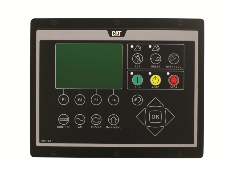
EMCP 4.4 Control Panel
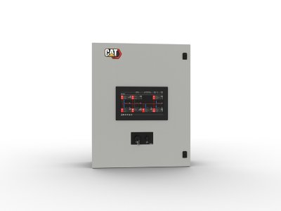
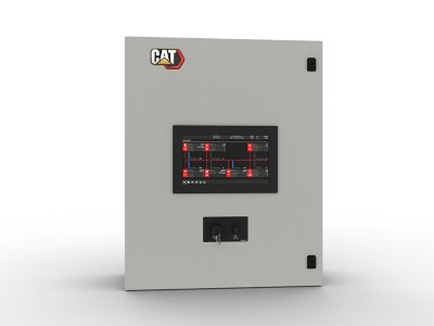
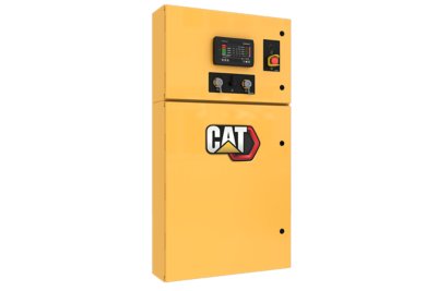
The EMCP 4 Control Panel provides all of the controls and system indicators in one easy to access interface.
Request a Quote
Have questions? Call 800.768.4200
EMCP 4 Controls
- Auto / Start / Stop Control
- Speed and Voltage Adjust
- Engine Cycle Crank
- Programmable Cycle Timer
- 24-volt DC operation
- Environmental sealed front face
- Text alarm/event descriptions
- Paralleling Mutiple Generator Set or Single Generator Set to Single Utility
Digital Indicators
- RPM
- DC volts
- Operating hours
- Oil pressure (psi, kPa or bar)
- Coolant temperature
- Volts (L-L & L-N), frequency (Hz)
- Amps (per phase & average)
- ekW, kVA, kVAR, kW-hr, %kW, PF
Warning / Shutdown Indicators
- Low oil pressure
- High coolant temperature
- Overspeed
- Emergency stop
- Failure to start (overcrank)
- Low coolant temperature
- Low coolant level
Programmable Protective Relaying
- Generator phase sequence
- Over/Under voltage (27/59)
- Over/Under Frequency (81 o/u)
- Reverse power (kW) (32)
- Reverse reactive power (kVAr) (32RV)
- Overcurrent (50/51)
- Overcurrent Thermal Damage Curve
- Current Balance (46)
- Bus Phase Sequence
Communications
- Twelve digital inputs
- Emergency stop pushbutton
- Five Analog output
- Seventeen digital outputs
- Two Analog Input
- customer data link (Modbus RTU)
- Accessory module data link
- Serial annunciator module data link
- Ethernet SCADA (Modbus TCP)
Compatibility
- Remote CAN annunciator
- Remote serial annunciator
- Local Annunciator
- Remote Monitoring Software
- Digital I/O module
- RTD module
- Thermocouple module
- Supervisory Control Panel
- Master Control Panel
Control
- Auto / Start / Stop control
- Remote start / stop
- Speed and voltage adjust
- Engine Cooldown Timer
- Local and remote emergency stop
- Engine Cycle Crank
- Programmable Cycle Timer
- Paralleling Multiple Generator Sets or Single Generator Set to Single Utility
Multiple Generator Set Paralleling
- Load sense / load demand
Single Gen to Single Utility Paralleling
- Emergency Mode with Closed/Open Return
- Standby Emergency
- Base Load Control
- Import/Export
- Soft Load/Unload
- Load shed/add (Up to Six Stages)
- LV/MV/HV capable (< 15kV)
- Genset & Utility Circuit Breaker control
Display
- A 480 x 320 pixel, 5.5 inch, white backlit graphical display denotes text alarm/event descriptions, set points, engine and generator monitoring, and is visible in all lighting conditions.
Generator Monitoring
- Voltage (L-L, L-N)
- Current (Phase)
- Average Volt, Amp, Frequency
- kW, kVAr, kVA (Average, Phase, %)
- Power Factor (Average, Phase)
- kW-hr, kVAr-hr (total)
Generator Protection
- Over/Under voltage (27/59)
- Over/Under frequency (81/OU)
- Generator phase sequence
- Bus phase sequence
- Overcurrent (50/51)
- Overcurrent (Thermal Damage Curve)
- Reverse Power (kW)(32)
- Reverse Reactive Power (kVAr) (32RV)
- Current Balance (46)
Engine Monitoring
- Engine speed (RPM)
- Battery voltage
- Oil pressure
- Oil Temperature
- Coolant temperature
- Multiple Language Support
- Crank attempt and successful start counter
- Run hours
- Enhanced engine monitoring (with electronic engines)
Engine Protection
- Low engine oil pressure (alarm)
- High engine oil temp (alarm and shutdown)
- High coolant temp (alarm and shutdown)
- Low coolant temp (alarm)
- Low coolant level (alarm)
- Overcrank
- Overspeed
- Control switch not in auto (alarm)
- Low, high, and weak battery voltage
Communications
- Primary and accessory CAN data links
- RS-485 annunciator data link
- Modbus RTU (RS-485 Half duplex)
- Modbus TCP (10BT Ethernet)
Inputs & Outputs
- Seventeen programmable digital outputs
- Two dedicated analog inputs
- Two programmable analog inputs
- Two dedicated digital inputs
- Twelve programmable digital inputs
Language Support
- Arabic, Bulgarian, Chinese, Czech, Danish, Dutch, English, Estonian, Finnish, French, German, Greek, Hungarian, Icelandic, Italian, Latvian, Lithuanian, Japanese, Norwgian, Polish, Portguese, Romanian, Russian, Slovak, Slovene, Spanish, Swedish & Turkish
Environmental
- Control module operating temperature: -40°C to 70°C
- Display operating temperature: -20°C to 70°C
- Humidity: 100% condensing 30°C to 60°C
- Storage temperature: -40°C to 85°C
- Vibration: Random profile, 24-1000 Hz, 6.0G ms
Need installed dimensions with enclosure and tank? See Model Configurations